← Back to Track Overview

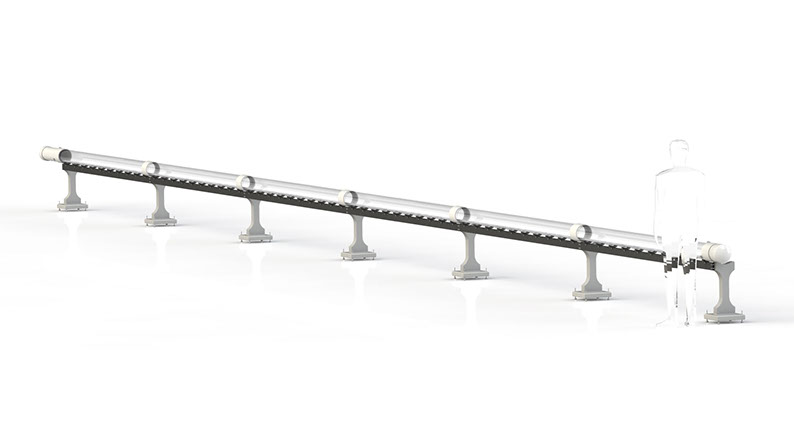
Rendering of final track design
Track Design
Major Subsystems and Parts:

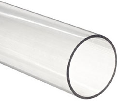
The tube consists of clear PVC sealed at 10ft junctions and inserted in plastic couplings as sleeves to prevent leakage. The inner diameter of the tube is 6.031in while the outer diameter is 6.625in. There are six tubes total: 10 feet for acceleration 40 feet for travel, and 10 feet for deceleration.

Pylons are made from molded concrete. A two-part wooden mold is used to form the concrete into the desired shape. Four adjustable leveling feet are implemented for alignment and to compensate for floor variation. Four threaded mounting points are located at the top of both sides of the pylon to mount support struts or other additions.

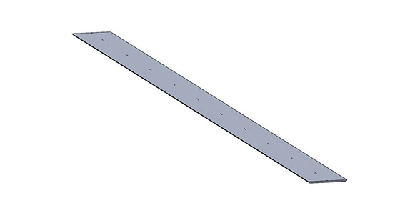
The Subtrack surface is a 3"w x 0.125"h aluminum bar, affixed to the tube support strut by adjustable supports at 1' intervals.

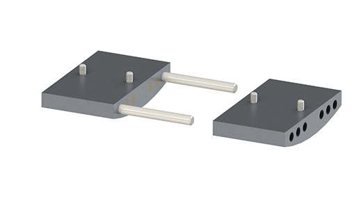
When assembling the 10' track segments, it will not be possible to access the ends of the track to join them together accurately. Therefore, the following setup was devised to automatically join and align the subtrack when two are fitted together. These brackets have neodymium magnets press fit into their faces, and one side has locating pins to align them.


The subtrack adjustment and support assembly is shown above Two vertical screws in ball joints control the pitch and height of the subtrack surface. These brackets (shown as the dark grey pieces), are 3D printed from ABS material. The ball socket is integral to the design of the top 3D printed piece, while the ball itself is a threaded brass ball.
We are a student group acting independently of the University of California. We take full responsibility for our organization and this web site.

